Product Description
| Product Model | SWL2.5, SWL5, SWL10, SWL15, SWL20, SWL25, SWL35, SWL50, SWL100, SWL120 |
| Product Description | Basic lifting component, compact structure, small size, light weight, no noise, safe and convenient, flexible use, high reliability, wide power source, multiple supporting functions, long service life |
| Usage | Single or combined use, can accurately control the adjustment of lifting or pushing height according to a certain program, can be directly driven by motor or other power, can also be manual |
| Lifting Efficiency and Load Capacity | Special and advanced technology has been developed to improve the overall performance of the jack |
| Structural Type | Type 1 – Screw moves axially; Type 2 – Screw rotates, nut moves axially |
| Assembly Type | Type A – Screw/nut moves upwards; Type B – Screw/nut moves downwards |
| Screw Head Type | Type 1 structure screw head: Type I (cylindrical), Type II (flange), Type III (threaded), Type IV (flat head); Type 2 structure screw head: Type I (cylindrical), Type III (threaded) |
| Transmission Ratio | Ordinary speed ratio (P), slow speed ratio (M), medium speed ratio (F) can be customized according to user requirements |
| Lifting Load Capacity | 2.5kN, 5kN, 10kN, 15kN, 20kN, 25kN, 35kN, 50kN, 100kN, 120kN |
| Screw Protection | Type 1 structure: basic type (no protection), anti-rotation type (F), with protective cover (Z), anti-rotation and protective cover (FZ); Type 2 structure: basic type (no protection) |
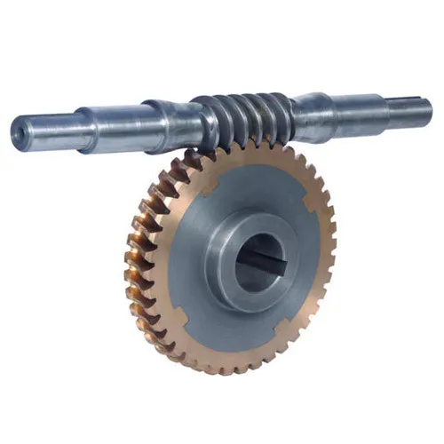
Product description: SWL series worm gear screw lift is a basic lifting component with many advantages such as compact structure, small volume, light weight, no noise, safety and convenience, flexible use, high reliability, wide power source, many supporting functions and long service life. It can be used singly or in combination, can adjust the height of lifting or advancing accurately according to certain procedures, and can be driven directly by electric motor or other power, or manually. In order to improve the efficiency and carrying capacity of SWL series worm gear screw lift, special and advanced technology is developed to improve the comprehensive performance of the lift to meet the requirements of the majority of customers. SWL series worm gear screw lift has different structure types and assembly types, and the lifting height can be customized according to the user’s requirements.
RFQ
Q:What information should I tell you to confirm speed reducer?
A: Model/Size, Transmission Ratio, Shaft directions & Order quantity.
Q:What if I don’t know which gear reducer I need?
A:Don’t worry, Send as much information as you can, our team will help you find the right 1 you are looking for.
Q:What should I provide if I want to order NON-STANDERD speed reducers?
A: Drafts, Dimensions, Pictures and samples if possible.
Q:What is the MOQ?
A: It is OK for 1 or small pieces trial order for quality testing.
Q:How long should I wait for the feedback after I send the inquiry?
A: Within 6 hours
Q:What is the payment term?
A:You can pay via T/T(30% in advance+70% before delivery), L/C ,West Union etc
| Standard or Nonstandard: | Nonstandard |
|---|---|
| Application: | Electric Cars, Motorcycle, Marine, Agricultural Machinery, Car |
| Spiral Line: | Right-Handed Rotation |
| Head: | Single Head |
| Reference Surface: | Toroidal Surface |
| Type: | ZK Worm |
| Samples: |
US$ 100/Piece
1 Piece(Min.Order) | |
|---|
How do you prevent backlash and gear play in a worm gear mechanism?
Preventing backlash and gear play is essential for maintaining the accuracy and performance of a worm gear mechanism. Here’s a detailed explanation of how to prevent backlash and gear play in a worm gear mechanism:
Backlash refers to the play or clearance between the teeth of the worm and the worm wheel in a worm gear mechanism. It can result in inaccuracies, positioning errors, and reduced efficiency. Here are some measures to prevent or minimize backlash and gear play:
- Precision manufacturing: Accurate and precise manufacturing of the worm and worm wheel is crucial to minimize backlash. High-quality machining techniques, such as grinding, can be employed to achieve precise tooth profiles and minimize any gaps between the teeth. Careful attention to the design and manufacturing tolerances can help reduce backlash.
- Tight meshing clearance: Proper adjustment of the meshing clearance between the worm and the worm wheel can help minimize backlash. The meshing clearance should be set as small as possible without causing interference or excessive friction. Close clearance ensures a tighter fit between the teeth, reducing the amount of play or backlash.
- Anti-backlash mechanisms: Anti-backlash mechanisms can be incorporated into the worm gear system to reduce or eliminate backlash. These mechanisms typically consist of spring-loaded components or adjustable devices that help compensate for any clearance between the teeth. They apply a constant pressure to keep the teeth engaged tightly, reducing the effects of backlash.
- Preload: Applying a preload to the worm gear system can help minimize backlash. Preload involves applying a slight compressive force or tension to the components, ensuring they remain engaged and eliminating any clearance. However, it is important to apply the appropriate preload to avoid excessive friction and wear.
- Lubrication: Proper lubrication is crucial for minimizing backlash and reducing gear play. Lubricants with suitable viscosity and properties should be used to ensure smooth and consistent operation of the worm gear mechanism. Good lubrication helps reduce friction, wear, and any potential clearance that can contribute to backlash.
- Regular maintenance: Regular inspection and maintenance of the worm gear mechanism can help detect and address any developing backlash or gear play. Routine checks can identify signs of wear, misalignment, or improper lubrication, allowing for timely adjustments or replacements to minimize backlash and maintain optimal performance.
It’s important to note that completely eliminating backlash in a worm gear mechanism may not always be possible or desirable. Some applications require a certain level of backlash to accommodate thermal expansion, compensate for positional errors, or allow for smooth operation. The acceptable level of backlash depends on the specific requirements of the application.
When implementing measures to prevent backlash and gear play, it is crucial to strike a balance between minimizing backlash and ensuring smooth, reliable operation. The specific techniques and approaches used to minimize backlash may vary depending on the design, manufacturing, and application requirements of the worm gear mechanism.
How do you ensure proper alignment when connecting a worm gear?
Ensuring proper alignment when connecting a worm gear is crucial for the smooth and efficient operation of the gear system. Here’s a detailed explanation of the steps involved in achieving proper alignment:
- Pre-alignment preparation: Before connecting the worm gear, it is essential to prepare the components for alignment. This includes cleaning the mating surfaces of the gear and shaft, removing any debris or contaminants, and inspecting for any signs of damage or wear that could affect the alignment process.
- Measurement and analysis: Accurate measurement and analysis of the gear and shaft alignment are essential for achieving proper alignment. This typically involves using precision alignment tools such as dial indicators, laser alignment systems, or optical alignment instruments. These tools help measure the relative positions and angles of the gear and shaft and identify any misalignment.
- Adjustment of mounting surfaces: Based on the measurement results, adjustments may be required to align the mounting surfaces of the gear and shaft. This can involve shimming or machining the mounting surfaces to achieve the desired alignment. Care should be taken to ensure that the adjustments are made evenly and symmetrically to maintain the integrity of the gear system.
- Alignment correction: Once the mounting surfaces are prepared, the gear and shaft can be connected. During this process, it is important to carefully align the gear and shaft to minimize misalignment. This can be done by observing the alignment readings and making incremental adjustments as necessary. The specific adjustment method may vary depending on the type of coupling used to connect the gear and shaft (e.g., keyway, spline, or flange coupling).
- Verification and final adjustment: After connecting the gear and shaft, it is crucial to verify the alignment once again. This involves re-measuring the alignment using the alignment tools to ensure that the desired alignment specifications have been achieved. If any deviations are detected, final adjustments can be made to fine-tune the alignment until the desired readings are obtained.
- Secure fastening: Once the proper alignment is achieved, the gear and shaft should be securely fastened using appropriate fasteners and tightening procedures. It is important to follow the manufacturer’s recommendations for torque values and tightening sequences to ensure proper clamping force and prevent any loosening or slippage.
It is worth noting that the alignment process may vary depending on the specific gear system, coupling type, and alignment tools available. Additionally, it is important to refer to the manufacturer’s guidelines and specifications for the particular gear and coupling being used, as they may provide specific instructions or requirements for alignment.
Proper alignment should not be considered a one-time task but an ongoing maintenance practice. Regular inspections and realignment checks should be performed periodically or whenever there are indications of misalignment, such as abnormal noise, vibration, or accelerated wear. By ensuring proper alignment during the initial connection and maintaining it throughout the gear’s operational life, the gear system can operate optimally, minimize wear, and extend its service life.
Are there different types of worm gears available?
Yes, there are different types of worm gears available to suit various applications and requirements. Here are some of the commonly used types:
Single Enveloping Worm Gear:
The single enveloping worm gear, also known as a cylindrical worm gear, has cylindrical teeth on the worm wheel that mesh with the helical thread of the worm. The teeth of the worm wheel wrap around the worm in a single enveloping manner. This design provides better contact and load distribution, resulting in higher load-carrying capacity and smoother operation. Single enveloping worm gears are commonly used in heavy-duty applications where high torque transmission is required.
Double Enveloping Worm Gear:
The double enveloping worm gear is a specialized type of worm gear that provides even greater load-carrying capacity compared to the single enveloping design. In a double enveloping worm gear, both the worm and the worm wheel have curved tooth profiles. The teeth of the worm wrap around the worm wheel while the teeth of the worm wheel wrap around the worm. This double enveloping action increases the contact area, improves load distribution, and enhances the gear’s efficiency. Double enveloping worm gears are used in applications that demand high torque and precision, such as aerospace and defense industries.
Non-enveloping Worm Gear:
The non-enveloping worm gear, also known as a non-throated worm gear, has a worm wheel with teeth that do not fully wrap around the worm. Instead, the worm wheel has straight or slightly curved teeth that engage with the helical thread of the worm. Non-enveloping worm gears are simpler in design and less expensive to manufacture compared to enveloping worm gears. They are commonly used in applications with moderate loads and where cost is a consideration.
Self-locking Worm Gear:
Self-locking worm gears are designed with a specific helix angle of the worm’s thread to provide a self-locking effect. This means that when the worm is not actively driving the worm wheel, the worm wheel is prevented from rotating backward and can hold its position securely. Self-locking worm gears find applications in systems where holding position or preventing backdriving is crucial, such as elevators, lifts, and certain industrial machinery.
These are just a few examples of the different types of worm gears available. The choice of worm gear type depends on factors such as the application requirements, load capacity, efficiency, and cost considerations.
editor by CX 2023-09-30


